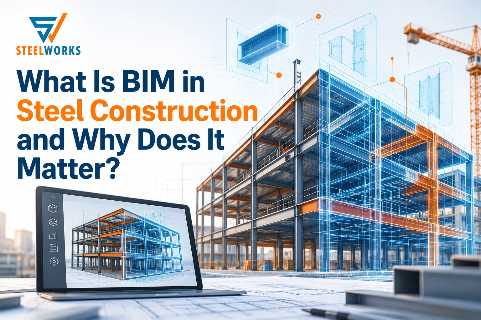
BIM in steel construction has moved from an optional upgrade to an operational baseline on any project where coordination, fabrication accuracy, and construction schedule matter. Building Information Modelling — what is BIM at its core — isn’t a drafting tool. It’s a methodology that replaces sequential, disconnected information with a single intelligent model that all project stakeholders work from simultaneously.
For steel construction specifically, the implications are significant. Steel fabrication has no margin for error — a fabricated member that doesn’t fit on site can’t be adjusted with a plane and a chisel. BIM in steel construction addresses this by resolving clashes, verifying connections, and producing fabrication-ready data before a single piece of steel is cut. SteelWorks applies BIM-based workflows across structural steel projects for industrial, commercial, and infrastructure clients. This guide covers how it works and why it matters.
How Does BIM Work in Steel Construction?
BIM modelling creates a three-dimensional information model that contains more than geometry. Each element — every beam, column, connection plate, bolt group, and weld — carries data: material specification, grade, length, weight, surface treatment, connection type, and fabrication sequence.
The model serves as the single source of truth for the project. BIM modelling ensures structural engineers, architects, MEP consultants, and fabricators all work from the same source rather than exchanging separate drawings that are never quite the same version. Changes in one discipline propagate through the model and flag conflicts with other disciplines automatically.
For structural BIM specifically, the model generates:
Fabrication drawings for each steel member
Shop drawing packages with connection details
Cut lists and material takeoffs
Erection sequences and assembly drawings
Clash detection reports against concrete, MEP, and architectural elements
How Is BIM Used for Steel Structures?
BIM for steel structures spans the entire lifecycle of the project – starting with design and continuing through fabrication and erection.
Design phase – the structural engineer creates the analytical model (in software such as STAAD, ETABS, or Robot Structural Analysis), then the BIM model is populated with the physical shape of all members, including the real-world geometry and connection data.
Detailing phase – the steel detailers operate directly within the BIM environment to create fully detailed connection data, plate sizes, bolt and weld specifications, and shop drawings, all tied to the same model. Tekla Structures is the primary steel detailing BIM software used in the industry.
Fabrication phase – steel BIM generates CNC data used to program automated cutting, drilling and marking machines in the fabrication shop. A fully model-based fabrication-to-machining workflow reduces human transcription errors.
Erection phase – erection drawings, piece marks and erection sequencing all come from a single model. The field crew references the same piece of information that drove fabrication, reducing RFIs during construction.
Key Benefits of BIM in Steel Construction
Clash detection before fabrication. The most expensive point to discover a conflict between a steel beam and a mechanical duct is when both are already installed. BIM in steel construction runs clash detection during the coordination phase — every conflict is visible in the model and resolved on screen rather than on site.
Fabrication accuracy. BIM-generated cut lists and CNC data produce steel members to tight dimensional tolerances. Fit-up problems at site are significantly reduced because the fabricated steel was produced from the same model that governs the connection geometry.
Faster procurement. Material takeoffs generated from the model are accurate and complete. Steel orders can be placed early in the project with confidence that the quantities and specifications are correct.
Improved coordination. Every sub-trade — concrete, steel, mechanical, electrical — reviews the same federated model. The benefits of BIM in cross-trade coordination are most visible in complex industrial and commercial projects where interference management would otherwise require extensive site rework.
Better project documentation. The model accumulates as-built information throughout the project. The final deliverable includes not just drawings but a populated model that serves as the basis for future maintenance and modification.
Role of Tekla Structures in Steel Detailing
Tekla Structures is the dominant platform for structural steel detailing in BIM workflows. It’s designed specifically for the steel detailing process — which makes it substantially more effective for this task than general architectural BIM tools.
Within Tekla, detailers model connections to full precision: bolt groups, weld details, cope cuts, stiffener plates, and gusset plates are all modelled as real geometry rather than represented symbolically. The software generates shop drawings, erection drawings, and CNC data directly from this geometry.
Tekla also handles the piece marking and shipping list process — every fabricated steel component gets a unique piece mark, and the system tracks the relationship between the model, the shop drawings, and the physical member through fabrication and erection.
For workflows that extend from design to shop floor to site, Tekla Structures provides the detailed model that bridges structural analysis and physical fabrication.
How BIM Improves Steel Fabrication and Quality Control
Quality control in steel fabrication has traditionally relied on manual inspection at multiple stages: checking dimensions after cutting, verifying connection holes before painting, confirming piece marks before shipping. BIM in steel construction changes where and how this checking occurs.
Model-based checking — connection geometry is checked against specifications before a mark is made on steel. Undersized plates and insufficient edge distances are flagged before fabrication begins.
CNC integration — BIM-generated CNC files drive the cutting and drilling machines directly. The human transcription step — where dimensional errors historically entered the process — is eliminated. The machine executes the model.
Traceability — piece marks generated by the model create a traceable record from design to fabrication to erection. If a quality issue surfaces at site, it’s traceable back to the specific shop order, the specific machine run, and the specific model revision.
Reduced rework — fabrication errors reaching site mean re-fabrication time, expedited delivery costs, and erection delay. Catching issues upstream in the model eliminates most of this.
The Future of BIM in Steel Construction
BIM adoption in Indian steel construction is accelerating, driven by:
Client mandates — large infrastructure and industrial clients increasingly require BIM deliverables as a contract condition.
4D and 5D BIM — time and cost dimensions added to the model allow erection sequencing and budget tracking from the same coordinated information source.
Digital twins — the BIM model updated with as-built information and integrated with facility management becomes a post-construction asset whose operational value exceeds its construction value.
Prefabrication integration — as modular construction grows, BIM provides the design-to-manufacture pipeline that makes complex prefabricated steel assemblies viable at scale.
Conclusion
BIM in steel construction is a risk reduction methodology that pays back through fewer fabrication errors, fewer site RFIs, faster erection, and better cross-trade coordination. Where fabrication accuracy determines project outcome, the BIM workflow is what makes that accuracy achievable.
SteelWorks integrates BIM-based detailing and fabrication workflows into their structural steel projects. Visit steelworks.in to learn more about their project capabilities.
FAQs
1. What is BIM in steel construction?
BIM in steel construction is a digital modelling process that helps plan, detail, fabricate, and erect steel structures using a shared information model.
2. What are the benefits of BIM in steel construction?
BIM helps reduce fabrication errors, detect clashes early, improve coordination, speed up procurement, and minimise on-site rework.
3. How is BIM used for steel structures?
BIM for steel structures supports design coordination, steel detailing, fabrication planning, CNC machine integration, and erection sequencing.
4. What is the role of Tekla Structures in steel detailing?
Tekla Structures helps detailers create precise steel connections, generate shop and erection drawings, and produce CNC-compatible fabrication data.
5. How does BIM improve steel fabrication accuracy?
BIM generates accurate dimensions, cut lists, and machine-ready data, reducing manual errors and improving traceability throughout fabrication and erection.