Water took the Chishoti crossing in J&K. A 2026 cloudburst wiped the map. Nobody had months to wait for custom concrete to dry while isolated villages suffered under awful conditions. Time was the absolute enemy. Within 12 short days, the 118 Road Construction Company of 35 BRTF under Project Sampark finished a 140-foot triple double reinforced span. You need a Bailey bridge when nature throws a tantrum. These quick-assembly steel structures hand the BRO a literal lifeline. Roads disappear under the mud. You fix the broken link. Pure muscle handles the rest.
Engineers still trust a design scratched onto scrap paper eight decades ago. It holds 100-ton loads. It is temporary bridge construction pushed to the absolute limit. The secret lies in simple physics, smart geometry, and zero wasted parts on the job site. We will look at the raw components and the exact load classes these setups handle. We will also clear up some stubborn industry myths. You will see why. Indian project planners keep returning to this classic system when the clock threatens to derail their entire schedule.
What Is a Bailey Bridge?
Origins in 1940–41
The genius of this crossing started on a desk. Donald Bailey drew his original proposal on the back of an envelope in 1940. Testing moved incredibly fast. A war demanded it. The design had to tolerate rough handling by exhausted soldiers working in pitch-black conditions. By November 26, 1942, the first operational bridge stood tall over the Medjerda River in Tunisia. Allied forces demanded these systems at a crazy scale during WWII. Factories went into overdrive. Upwards of 600 independent companies produced 500,000 tons of raw material. You ended up with about 700,000 panels ready to ship out.
Why It Still Matters
A modular steel bridge makes sense in the mud. Logistics rule the site. Every single part swaps out with another. Humans carry the weight. A small crew builds the crossing in terrible spots. Cranes get stuck. People keep walking. You put it up, cross the gap, and pack the pieces away for the next job. Disaster relief is its main civilian job now. It fixes the gap when landslides lock a community out of the modern world.
Core Components
The Panel
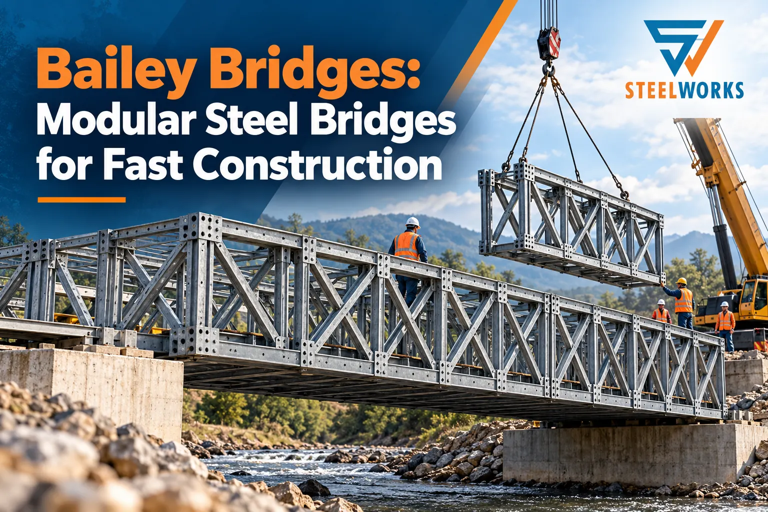
The panel does the heavy lifting. Look at the basic steel rectangle. It measures 10 feet long and 5 feet high. It weighs 570 pounds. Four or six workers carry it without lifting gear. The corners hold the secret. Male and female lugs sit on the top and bottom chords. Sections snap together end-to-end. The panel bridge relies entirely on this simple, repetitive geometry.
Transoms, Stringers and Deck
The deck system ties everything together securely. Steel transoms sit horizontally across the bottom of the panels to form cross beams. These measure 19 feet long. Between these transoms run 10-foot stringers to support the deck longitudinally. The old days featured timber trusses for the roadway surface. Wood rots and splinters under heavy tires. A prefabricated steel bridge relies on heavy steel decks today. Modern trucks need that extra support. Steel grips the tires and handles the rain much better than timber ever did.
Pins, Braces and Bearings
Little pieces do heavy jobs here. Workers drive panel pins straight into the chord lugs to link the sections. Sway braces fight off sideways movement and wind shear. A strong valley crosswind will test those braces immediately. End posts take the heavy vertical loads and push them down into the earth. Base plates and bearings then seat the whole assembly gently onto the prepared abutments. Without these bearings, the steel would just dig into the dirt.
Table A: Component Reference
| Component | Function | Key figure |
|---|---|---|
| Panel | Main load-carrying truss unit | 10 ft × 5 ft, 260 kg |
| Transom | Cross beam carrying the deck | 19 ft long |
| Stringer | Longitudinal deck support | 10 ft long |
| Panel pin | Joins panels end to end | Driven into chord lugs |
| Sway brace | Resists sideways movement | Two per bay |
| End post | Transfers load to bearings | Male and female types |
| Bearing and base plate | Seats the bridge on abutments | One per truss line |
Girder Configurations
Trusses and Storeys
You add strength to a Bailey bridge by grouping panels. Builders count trusses for the sides. They count storeys for the height. An SS setup means single truss, single storey. Add more panels to handle heavier trucks or to stretch a longer single span. A TT configuration uses three thick trusses and three high storeys for maximum strength. You see these giant setups when hauling industrial equipment across a wide river.
Reinforced Chords
Sometimes stacking panels falls short. For extreme weights like IRC Class 70R loading, builders use panels with reinforced chords. They add an R suffix to the name. You will see setups like SSR, DDR, or TDR. This added reinforcement stops the bottom chords from failing under the intense stress of heavy military or industrial traffic. Engineers do not guess with these numbers. They calculate the exact shear force before ordering the panels.
Table 1: Configurations
| Configuration | Trusses per side | Storeys | Typical use |
|---|---|---|---|
| SS | 1 | 1 | Light vehicles, footbridges |
| DS | 2 | 1 | Light to medium traffic |
| TS | 3 | 1 | Medium traffic, short spans |
| DD | 2 | 2 | Medium traffic, longer spans |
| TD | 3 | 2 | Heavy traffic |
| DT | 2 | 3 | Long spans, moderate loads |
| TT | 3 | 3 | Heaviest loads, longest spans |
Launching a Prefabricated Steel Bridge
The Launching Nose
Pushing hundreds of tons of steel over a river without a far-side crew sounds impossible. It is not. You build a launching nose. Crews angle the front part up slightly with launch links and push the skeleton forward on rollers. That upward angle actively fights gravity. It perfectly compensates for natural sag and lands the nose smoothly onto the far abutment rollers. The crew just keeps pushing from the safe side of the bank.
Rollers and Balance
The whole operation glides forward on plain and rocking rollers. Balance dictates everything during the push. The tail of the modular steel bridge stays on the near bank. It must outweigh the nose hanging in the air. Playground seesaw rules apply here. The steel stays out of the water. It is the absolute secret to such quick assembly.
Launch Sequence
The full field process runs exactly like this: Site survey → abutment preparation → roller setup → bay assembly with nose → push-out → jacking onto bearings → deck and ramp fitting → load test.
Load Classes and Spans
Load Class Basics
Indian civil engineers follow strict national highway codes. They plan for IRC Class 70R loading. This rating means the Bailey bridge holds a 70-tonne tracked vehicle. It also holds a 100-tonne wheeled assembly without trouble. A properly built structure handles this intense daily stress easily.
Span Versus Configuration
Span length directly dictates the needed panel setup. A standard rig of three panels across and two high can carry battle tanks over a 200-foot single span. Single spans do have physical limits, though. Longer crossings require intermediate piers in the water. For example, the gigantic 788-metre Hobart crossing built in 1975 relied heavily on intermediate supports to clear the wide Derwent River.
Temporary Bridge Construction in India
Border Road Builds
Mountain roads wash out constantly during the monsoon season. Up in the tricky hill states, the BRO counts on the Bailey bridge heavily. They recently threw a 180-foot TDR span across a huge gap in the remote Kurung Kumey district of Arunachal Pradesh under Project Arunank. Workers use the launching nose technique to shove heavy steel across dizzying gorges. It keeps isolated outposts connected to the mainland.
Flood and Landslide Cases
Rain washes the main road away. That is when disaster relief starts. The 2024 Wayanad landslides tore up the landscape entirely. The Indian Army stepped up fast. They rapidly built a 190-foot span at Mundakkai. This crossing let heavy excavators and rescue teams finally reach the trapped communities safely.
Table 2: India Timeline
| Year | Location | Detail |
|---|---|---|
| 1996 | Ranni, Kerala | First civilian use in India, over the Pamba river |
| 2018 | Mumbai | FOBs at Elphinstone Road, Currey Road and Ambivli |
| 2024 | Wayanad, Kerala | 190 ft, built after landslides |
| 2026 | Chishoti, J&K | 140 ft TDR, completed in 12 days |
| Recent | Kurung Kumey, Arunachal Pradesh | 180 ft TDR |
Myths Worth Correcting
“No Welding Involved”
Many people think the whole thing is just pinned together in the field by hand. This is totally false. While the site joints use pins for fast assembly, the panel bridge component itself is made of heavily welded high-tensile steel straight from the factory floor.
“Invented in 1938”
The timeline gets muddy sometimes. A few books wrongly name 1938 as the start for the prefabricated steel bridge. The real story took a little longer. Donald Bailey submitted an early idea in 1936. He drew his famous sketch in 1940. The first physical prototype took abuse in 1941.
“Only a Stopgap”
These solid structures frequently outlive their temporary labels. Look at Port Hope, Canada. A modular steel bridge went up there in 1984. Traffic needed a quick fix. It actually stayed in daily service until 2017.
Limits to Plan For
Deflection and Sag
A Bailey bridge is going to sag. That is just reality. The designed camber and a tiny bit of wiggle room in the pin-holes across the 10-foot bays cause this drop. Engineers run the numbers on this deflection so the deck acts right when heavy trucks roll over.
Corrosion and Pin Wear
Steel demands maintenance. Mandatory inspections check for rust. Fatigue happens over time. Owners invest in galvanizing. Painting the panels fights the rain. You plan for routine pin replacement. Metal parts take serious abuse from shifting forces.
Deck Wear and Noise
Steel decks are loud. They rattle constantly under vehicular traffic. This intense noise, along with the steady wear on the decking components from heavy trucks, is one primary reason owners eventually plan a permanent concrete replacement for temporary bridge construction.
Steelworks: Your Steel Partner
Full-Service Fabrication
Steelworks delivers complete, end-to-end solutions for heavy infrastructure. We fabricate major steel bridges. This includes NH bridges, railway bridges, and camelback girders. We also build FOBs. Skywalks, ramps, and cable-stayed structures round out the list. We supply complete PEBs and handle complex customized fabrication projects. We specialize in tunnel formworks, a product line Steelworks has confidently led for over 40 years. We walk you through every phase of a prefabricated steel bridge build. We handle the initial design and conceptualization. Then we move straight into fabrication and manufacturing. We finish the job with surface protection, painting, erection, and commissioning.
Approvals and Clients
Trust requires proof. We hold RDSO vendor approval for our two group entities. We have a proven track record delivering steel structures for major government and infrastructure clients. These include NHPC, BHEL, DMRC, and the CPWD.
Conclusion
The Bailey bridge fundamentally changed field engineering forever. Its speed and its modularity rewrote the rulebook. The incredible Indian field record proves it remains the top choice for urgent crossings. From high border roads to flooded valleys, these steel panels deliver access when failure is out of the question. You cannot argue with eighty years of proven success.
Short-term crossings rely on this pinned system. Permanent infrastructure demands dedicated steel fabrication. If your project requires temporary bridge construction or permanent structural steel, reach out today. Steelworks knows metal. We have handled these exact manufacturing demands for over forty years. Drop your details into our enquiry form to discuss your specific bridge or tunnel formwork needs. We get the steel right the first time.
Acronyms Used
| Acronym | Full form |
|---|---|
| BRO | Border Roads Organisation |
| BRTF | Border Roads Task Force |
| IRC | Indian Roads Congress |
| RDSO | Research Designs and Standards Organisation |
| PEB | Pre-Engineered Building |
| FOB | Foot Over Bridge |
| NH | National Highway |
| WWII | World War II |
| J&K | Jammu and Kashmir |
| SS | Single Single |
| DS | Double Single |
| TS | Triple Single |
| DD | Double Double |
| TD | Triple Double |
| DT | Double Triple |
| TT | Triple Triple |
| SSR | Single Single Reinforced |
| DDR | Double Double Reinforced |
| TDR | Triple Double Reinforced |
| NHPC | National Hydroelectric Power Corporation |
| BHEL | Bharat Heavy Electricals Limited |
| DMRC | Delhi Metro Rail Corporation |
| CPWD | Central Public Works Department |
| CTA | Call To Action |
FAQs
Q: Is a modular steel bridge only meant for temporary bridge construction?
A: No. While designed for rapid temporary bridge construction, a properly maintained modular steel bridge handles daily civilian traffic for decades.
Q: How much weight can a prefabricated steel bridge support?
A: A fully reinforced prefabricated steel bridge carries 100-ton wheeled loads safely.
Q: Why is temporary bridge construction so fast with this specific system?
A: Fast temporary bridge construction relies on standardized parts. Crews manually pin the modular steel bridge components together using basic hand tools.
Q: Do engineers need heavy cranes to install a modular steel bridge?
A: No. Crews push the modular steel bridge across gaps using rollers, completely bypassing crane requirements during temporary bridge construction.
Q: Are prefabricated steel bridge components welded together on the job site?
A: No. Factories weld the heavy prefabricated steel bridge panels beforehand. Field workers exclusively use steel pins to connect the structural joints.